How to Use constant power IC in power adapters
A constant power IC in power adapters is an advanced integrated semiconductor chip that dynamically balances output voltage and current to deliver a stable, pre-defined maximum wattage across varying electrical loads. Product designers often face unexpected power supply shutdowns when their devices demand brief current spikes. These random resets trigger device failures, delay system boots, and result in terrible reviews from end-users who blame your product. Utilizing a robust constant power IC in power adapters bridges this performance gap by scaling voltage down to sustain uninterrupted power flow.
What Is a Constant Power IC in Power Adapters?
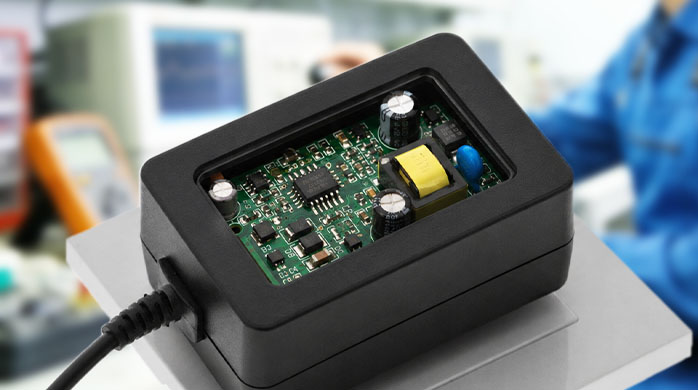
The constant power IC in power adapters is a dedicated regulator that keeps output wattage constant by adjusting voltage and current in real time. Unlike standard units that shut down during overload, this integrated circuit dynamically maps a safe volt-amp curve. This keeps the power adapter operating seamlessly even when the connected system draws a peak load. It is a fundamental building block for modern, highly resilient electronic devices.
It bridges the gap between raw power demand and safety constraints. By monitoring feedback loops at microsecond intervals, it ensures that your system never exceeds its thermal limits. This eliminates the need for massive thermal dissipation schemes.
What makes it unique?
When you compare a standard controller to an advanced constant power IC, the difference lies in control flexibility. Standard models operate in a binary on-off mode that leaves no room for brief overload tolerances.
Let’s look closer:
-
It features dual-loop control monitoring both current and voltage.
-
It dynamically scales voltage to keep your connected device energized.
-
It reduces total hardware footprint by optimizing current management.
Key Takeaway: Using a constant power IC ensures your hardware rides through momentary load spikes smoothly, saving you from constant system resets.
| Feature | Standard Controller | Constant Power IC |
|---|---|---|
| Output Behavior | Trips instantly | Adapts voltage and current |
| Overload Profile | Binary shut-off | Controlled continuous power |
| Footprint Size | Large and heavy | Compact and efficient |
Understanding these functional differences helps you make informed hardware design decisions.
Why Is a Constant Power IC in Power Adapters Important?
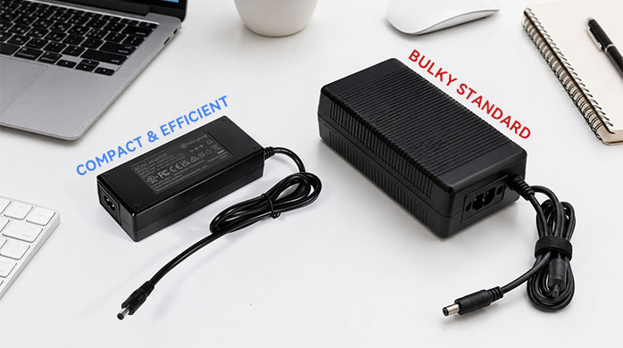
A constant power IC in power adapters is important because it prevents system designers from having to over-specify or enlarge their power supply components. When you design without it, you are forced to choose a larger transformer to handle brief current surges. This drives up production bills of materials and makes the final charger bulky. By integrating this chip, you can achieve excellent performance in a fraction of the size.
Additionally, compact power designs are much more appealing to modern end-users. A smaller adapter is easier to pack, transport, and plug into crowded wall sockets. This gives your electronic product a distinct competitive edge in the marketplace.
How does it cut design costs?
If you want to keep production budgets low, avoiding oversized components is your best strategy. Standard adapters use larger magnetic parts purely to support transient peak loads.
Think about this:
-
It permits smaller, more cost-effective inductors and transformers.
-
It decreases secondary-side filter capacitor requirements.
-
It minimizes thermal dissipation hardware like bulky aluminum heatsinks.
Key Takeaway: Integrating this IC allows you to use highly optimized components, reducing your bill of materials while improving portability.
| Parameter | Standard Design | Optimized IC Design |
|---|---|---|
| Transformer Dimension | Oversized for peaks | Sized for continuous average |
| Bill of Materials (BOM) | Expensive | Highly cost-optimized |
| Adapter Weight | Heavy and cumbersome | Lightweight and portable |
Let’s examine the actual physics behind this dynamic power regulation system.
How Does a Constant Power IC in Power Adapters Work?
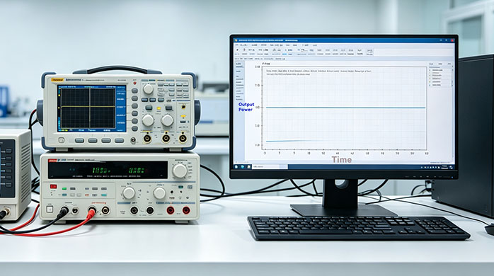
The constant power IC in power adapters works by continuously monitoring output current and voltage loops to regulate total wattage. It calculates real-time power dissipation using high-speed internal arithmetic logic. When output current begins to spike, the feedback loop drops the voltage proportionally. This action maintains a steady, safe operating power envelope on the V-I curve.
The primary controller adjusts the pulse width modulation duty cycle on every cycle. This high-frequency tracking ensures that your circuit never wanders into unsafe thermal zones. The transitions are incredibly fast, occurring within microseconds to protect delicate silicon parts.
What happens in the feedback loop?
To understand the performance, you need to look at how feedback signals travel across the isolation barrier. The IC reads secondary-side current through a low-loss shunt resistor.
Here is how it works:
-
An optocoupler transmits high-precision error signals to the primary side.
-
The controller adjusts the switching frequency instantly based on demand.
-
The system shifts smoothly between voltage and current regulation.
Key Takeaway: High-speed real-time loops ensure that your power output remains strictly clamped, avoiding voltage collapses or over-temperature hazards.
| Operating State | Voltage Control | Current Control | Power Delivery |
|---|---|---|---|
| Normal Mode | Active regulation | Monitoring only | Variable (Power is below maximum) |
| Power Boundary | Drooping dynamically | Active adjustment | Locked (Power is at maximum) |
| Short Circuit | Suppressed | Active limiting | Controlled foldback |
Let’s explore how this exact control mechanism resolves common field failures.
What Problems Can a Constant Power IC in Power Adapters Solve?
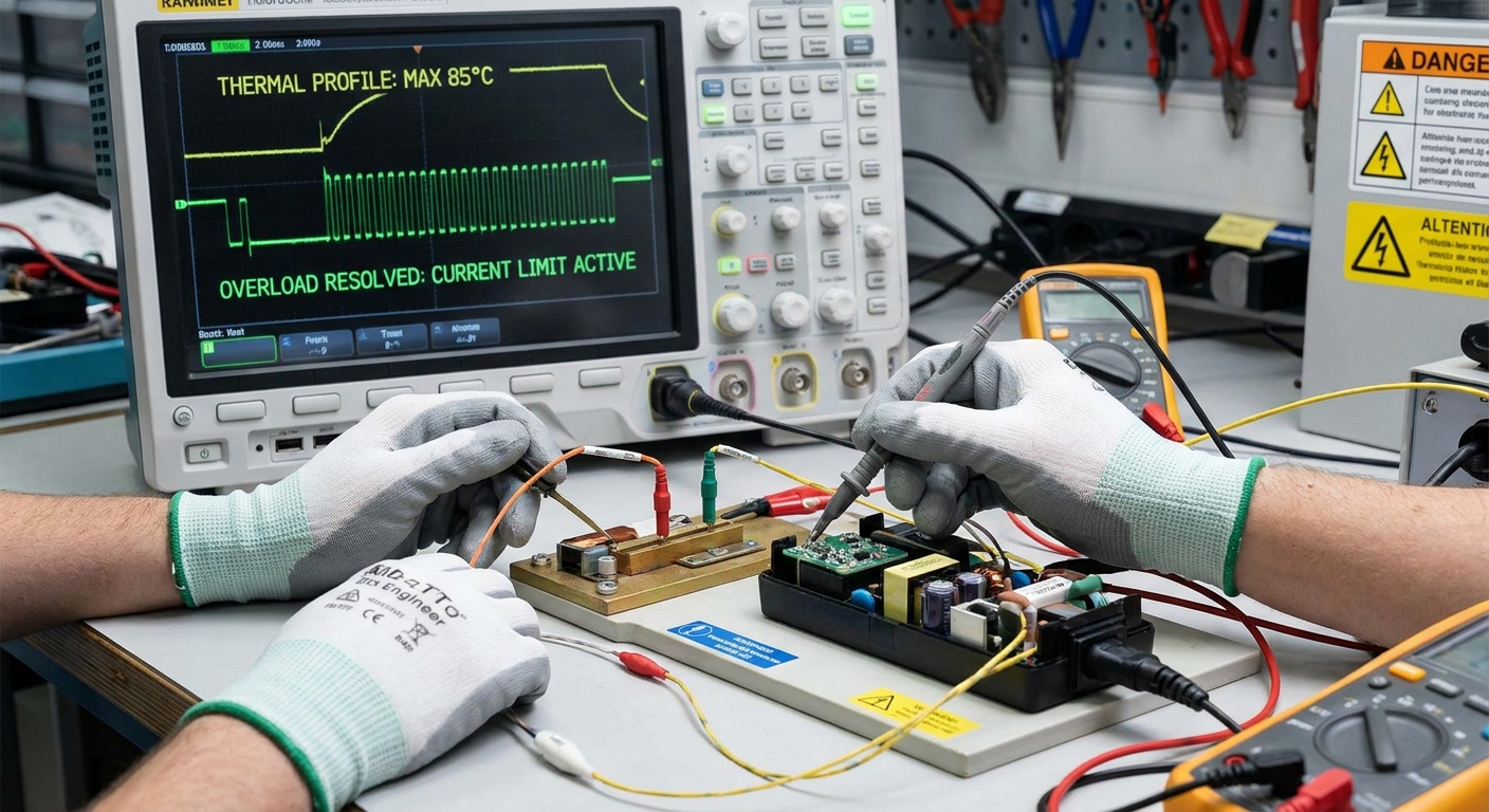
A constant power IC in power adapters solves frequent startup interruptions and sudden power cutoffs caused by highly dynamic loads. Devices like smart home locks or motorized tools require massive energy rushes when they first turn on. Standard adapters misinterpret this high inrush current as a dangerous short-circuit. They trip their safety switches immediately, leaving your device completely dead.
By adjusting voltage instead of cutting power, the IC keeps the supply line open. This behavior allows motors and large capacitor banks to boot up successfully. It saves your engineering team from chasing elusive power-delivery bugs.
How does it prevent false trips?
When you are powering dynamic hardware, false overcurrent trips can cause constant headaches. The IC distinguishes between an actual hardware fault and a temporary motor startup rush.
But wait, there is more:
-
It allows controlled, temporary voltage sags to deliver peak currents.
-
It charges massive capacitive loads without entering recursive hiccup loops.
-
It avoids unwanted device restarts during high-speed load transitions.
Key Takeaway: This dynamic current management solves startup dropouts, ensuring that your high-draw systems power up reliably every single time.
| Issue | Traditional Adapter Result | Constant Power Adapter Result |
|---|---|---|
| Motor Inrush Spike | Shuts down immediately | Safely boots motor using droop |
| Soft Short Circuit | High risk of melting parts | Restricts power to safe bounds |
| Heavy System Load | Resets the system | Maintains stable output rail |
Now let’s explore how these benefits directly influence overall voltage stability.
How Does a Constant Power IC in Power Adapters Improve Output Stability?
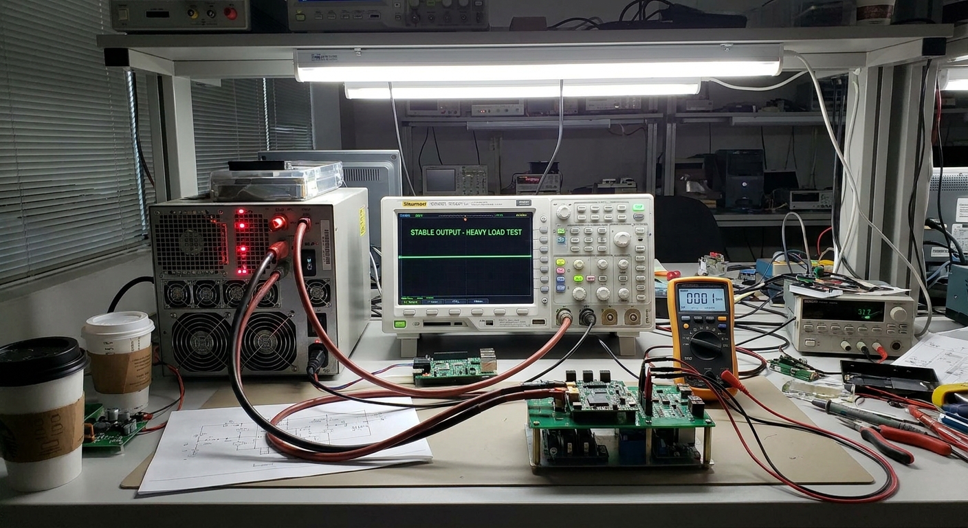
The integration of a constant power IC in power adapters improves output stability by damping transient oscillations during rapid load shifts. Fast-switching circuits often suffer from severe voltage ringing and sag when power demands change instantly. This IC uses advanced compensation networks to absorb these electrical shocks. The result is a clean, steady voltage rail that shields downstream microchips from damage.
It actively prevents voltage spikes when a heavy load is suddenly removed. Standard controllers often experience high voltage overshoot in these moments. This IC keeps the voltage tightly clamped, protecting your product from electrical overstress.
Why overshoot reduction matter?
If you want your downstream circuits to survive for years, keeping voltage overshoot low is vital. Sudden spikes can degrade sensitive capacitors and trigger integrated circuit failures.
Consider this point:
-
It limits maximum transient overshoot to extremely low margins.
-
It speeds up voltage recovery times during rapid step-load shifts.
-
It minimizes reliance on expensive, bulky external smoothing capacitors.
Key Takeaway: Tighter transient control protects your downstream components from voltage surges, enhancing your system’s lifetime.
| Parameter | Slow Standard Loop | Fast Constant Power Loop |
|---|---|---|
| Recovery Speed | More than 2.0 milliseconds | Less than 0.5 milliseconds |
| Transient Voltage Sag | Up to 15% sag | Kept under 5% sag |
| Output Ringing | High harmonic oscillation | Heavily damped waveform |
Let’s look at how this stability extends to critical safety protections.
How Does a Constant Power IC in Power Adapters Support Overload Protection?
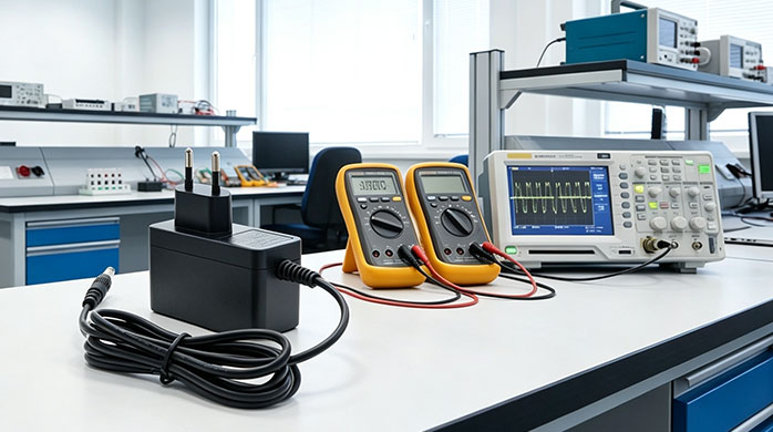
A constant power IC in power adapters supports overload protection by mapping a strict current foldback safety boundary. If an electronic device experiences a continuous fault, traditional power bricks can overheat and pose fire hazards. This IC monitors safety boundaries and reduces current as output impedance collapses. This keeps total thermal dissipation within perfectly safe physical limits.
The system does not rely on a simple fuse or latch-off switch. It manages safety dynamically, ensuring your hardware remains protected without needing manual resets. Once the overload fault is removed, normal voltage output recovers automatically.
How does current foldback work?
When you run into a persistent short-circuit, control loops must restrict current flow immediately. The IC automatically transitions into a foldback state, scaling down both current and voltage.
Let’s look closer:
-
It limits primary MOSFET current on a precise cycle-by-cycle basis.
-
It prevents localized hotspot creation on the PCB.
-
It utilizes on-chip thermal shutdown sensors as a secondary shield.
Key Takeaway: Intelligent safety curves safeguard both your charger and connected device from overheating during severe faults.
| Overload Level | System Behavior | Safety Status |
|---|---|---|
| Minor (105-120%) | Voltage drops, current scales | Continuous safe running |
| Major (120-150%) | Constant current active | Restricted thermal build-up |
| Short Circuit | Foldback and auto-recovery | Safe shutdown, zero fire risk |
Now let’s explore which specific industries benefit the most from this protection.
Which Applications Need a Constant Power IC in Power Adapters?
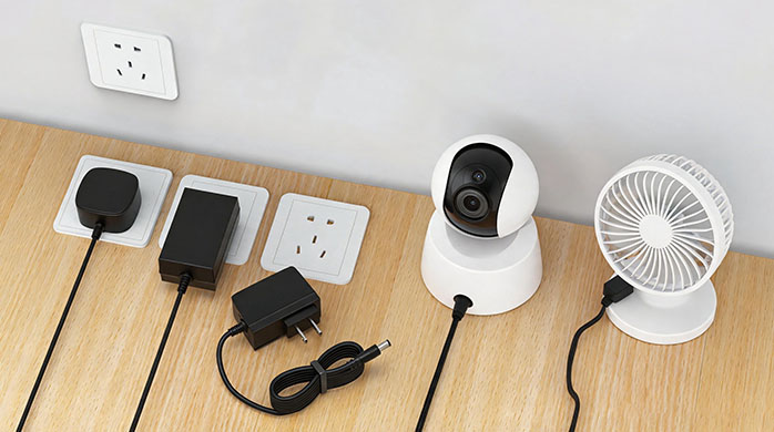
Many high-performance systems require a constant power IC in power adapters to handle transient power spikes and continuous motor draws. Smart home systems, networking hardware, and modern medical devices frequently engage solenoids, relays, or pumps. These mechanical actions demand instant, high-energy pulses that standard chargers simply cannot sustain. Our specialized adapters keep these vital services running smoothly.
Fast battery chargers also benefit greatly from this exact technology. Delivering maximum power without tripping speeds up overall charging cycles. This creates a superior experience for the end-user.
Is it essential for IoT setups?
If you are building smart locks, security hubs, or connected cameras, continuous power is non-negotiable. A momentary drop in adapter voltage can trigger an entire system reboot.
Think about this:
-
It maintains continuous camera feeds during nighttime sensor activation.
-
It supplies sufficient rush current to actuate smart door solenoids.
-
It prevents data corruption in IoT hubs caused by low-voltage drops.
Key Takeaway: Implementing this chip in your IoT adapters prevents random reboots, keeping your connected devices online and secure.
| Application | Power Spike Source | Why Constant Power Is Crucial |
|---|---|---|
| Smart IoT Locks | Motor and solenoid actuation | Prevents system micro-resets |
| Medical Pump | Continuous fluid driver motor | Delivers uninterrupted medical therapy |
| Battery Charger | Variable impedance load | Optimizes safe battery charge speeds |
Let’s outline how your team can select the best IC for your project.
How Should Engineers Select a Constant Power IC in Power Adapters?
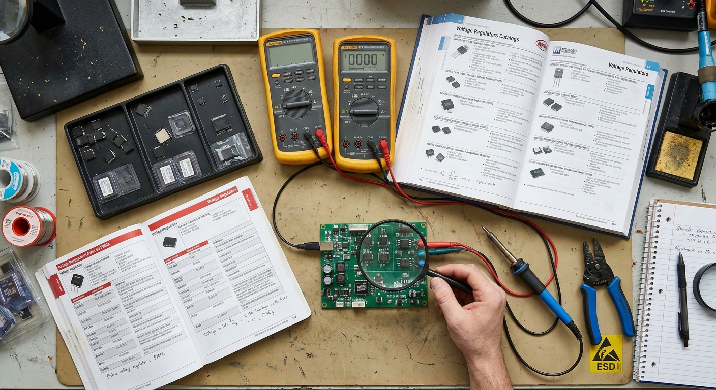
Choosing the correct constant power IC in power adapters requires evaluating your system’s dynamic load profiles and safety standard requirements. Your team must analyze the peak current magnitudes, typical duty cycles, and operating temperatures. Standard off-the-shelf components might not match the specific voltage-current curves of your hardware. A tailored approach ensures both compliance and peak operational efficiency.
It is also vital to evaluate standby power requirements. Global standards like Energy Star mandate extremely low power draw when your device is idling. Selecting an IC with a low standby footprint saves you from painful compliance redesigns.
What specifications matter most?
When you are reviewing datasheets, focus closely on loop response speeds and on-chip protection schemes. An IC with primary-side regulation will reduce your total bill of materials.
Here is the thing:
-
Integrated frequency jittering simplifies compliance with strict EMI/EMC rules.
-
Primary-Side Regulation (PSR) completely removes the need for an optocoupler.
-
Adjustable V-I curves let you tune performance to your exact motor loads.
Key Takeaway: Selecting an IC with integrated regulation and EMI suppression streamlines your certification process, saving engineering time.
| Selection Feature | Recommended Specification | Direct Project Benefit |
|---|---|---|
| Idle Power Draw | Under 30 milliwatts | Passes Energy Star Level VI easily |
| Frequency Jittering | On-chip integration | Drastically reduces EMI filter cost |
| Primary-Side Feedback | PSR topology | Drops secondary component count |
Once selected, these power systems must undergo strict quality testing.
How Is a Constant Power IC in Power Adapters Tested During Production?

Testing a constant power IC in power adapters during mass manufacturing demands high-precision dynamic electronic load profiling. Every unit must be verified under actual load-stepping conditions to map its V-I curve. This step ensures that the transition points between constant voltage and constant power are highly accurate. Adapters that exhibit incorrect curves are instantly rejected by automated testing machinery.
Quality assurance also requires high-temperature burn-in tests. We run the adapters at maximum rated capacity inside specialized thermal chambers. This process reveals any early-life component failures before the chargers ship to your customers.
How are V-I boundaries checked?
When you test on the line, you must use dynamic electronic loads to sweep impedance rapidly. This verifies that the IC activates its power clamping loop at the exact target current.
Here is how it is done:
-
The ATE sweeps output resistance from open to a hard short circuit.
-
High-speed sensors measure voltage droop to verify the CP slope accuracy.
-
Automated test sequences log calibration values for strict quality records.
Key Takeaway: Automated dynamic load testing on the production line guarantees that every adapter operates safely within design specs.
| Production Test Phase | Testing Equipment | Quality Target |
|---|---|---|
| Dynamic Curve Sweep | Fast electronic loads | Verify CP curve within 5% limits |
| Environmental Burn-in | Thermal soak chamber | Eliminate early-life semiconductor failures |
| Hard Short Test | Low-impedance switch | Confirm immediate current foldback |
Let’s look at how advanced technologies can push these adapter designs even further.
How Can Manufacturers Optimize a Constant Power IC in Power Adapters?
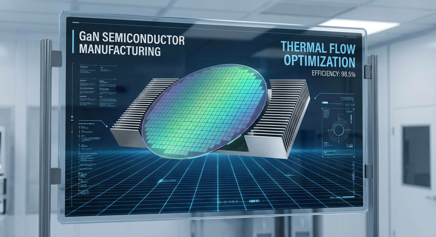
To maximize efficiency, a constant power IC in power adapters can be paired with wide-bandgap semiconductors like Gallium Nitride. GaN switches allow much higher operating frequencies and lower conduction losses compared to silicon. This allows us to reduce transformer sizes even further. The result is a highly efficient power brick that runs cool to the touch.
Implementing synchronous rectification on the secondary side also boosts efficiency. By replacing Schottky diodes with active MOSFET switches, we minimize energy waste. This strategy represents the absolute peak of modern power adapter design.
Why upgrade to GaN technology?
If you want to achieve the highest power density possible, moving to GaN is the logical step. It reduces power losses by more than half compared to standard silicon designs.
But wait, there is more:
-
It enables ultra-compact housings that are perfect for modern travel.
-
It reduces thermal dissipation requirements, allowing sleeker designs.
-
It boosts conversion efficiency to outstanding levels above 94%.
Key Takeaway: Pairing GaN transistors with synchronous rectification represents the ultimate combination for compact, ultra-efficient power adapters.
| Technology Level | Key Silicon Parts | Typical Efficiency | Thermal Profile |
|---|---|---|---|
| Legacy Setup | Silicon and Schottky Diode | 82% to 87% | High operating temperatures |
| Standard Upgrade | Silicon and Active Switch | 88% to 91% | Moderate thermal footprint |
| Premium Design | GaN Switch and Active Switch | 92% to 95% | Exceptionally cool running |
Now let’s summarize these architectural findings and review next steps.
Conclusion
At Merryking, we specialize in delivering globally certified, high-efficiency power solutions engineered with premium constant power IC technology. Over the past 20 years, our team has helped hundreds of B2B partners across industrial, medical, and consumer electronics solve complex startup resets and power-density challenges. Ready to eliminate random resets and elevate your device’s power delivery? Contact us today to discuss your custom project specifications with our senior engineering team.
FAQs
Can I replace a standard charger with a constant power adapter?
Yes, you can do so safely and it will significantly improve startup reliability for complex loads. A constant power adapter is backward-compatible with most systems, provided the nominal voltage matches your device’s inputs.
What’s the best way to choose the maximum power limit?
The best way is to match the threshold to the continuous thermal dissipation limit of your components. This ensures that the power brick never overheats during sustained peaks, protecting both internal circuits and the external cable.
How do I know if my system needs a constant power adapter?
You need one if your hardware contains motors, solenoids, or high-capacity input filters that cause standard adapters to shut down on boot. If your product is experiencing random restarts during peak activities, integrating this IC is your most cost-effective fix.
Can I use these adapters for medical-grade equipment?
Absolutely, they are ideal for medical systems where continuous operation is critical to patient safety. Devices like miniature pumps or monitoring hubs utilize these ICs to prevent power interruptions during momentary current transients.
How do I know if my design layout supports proper cooling?
You should check if your PCB integrates copper thermal vias combined with dual-sided layouts. This setup spreads localized heat from the primary switches across a wider surface area, keeping external enclosure temperatures extremely safe.